
New platform – new process

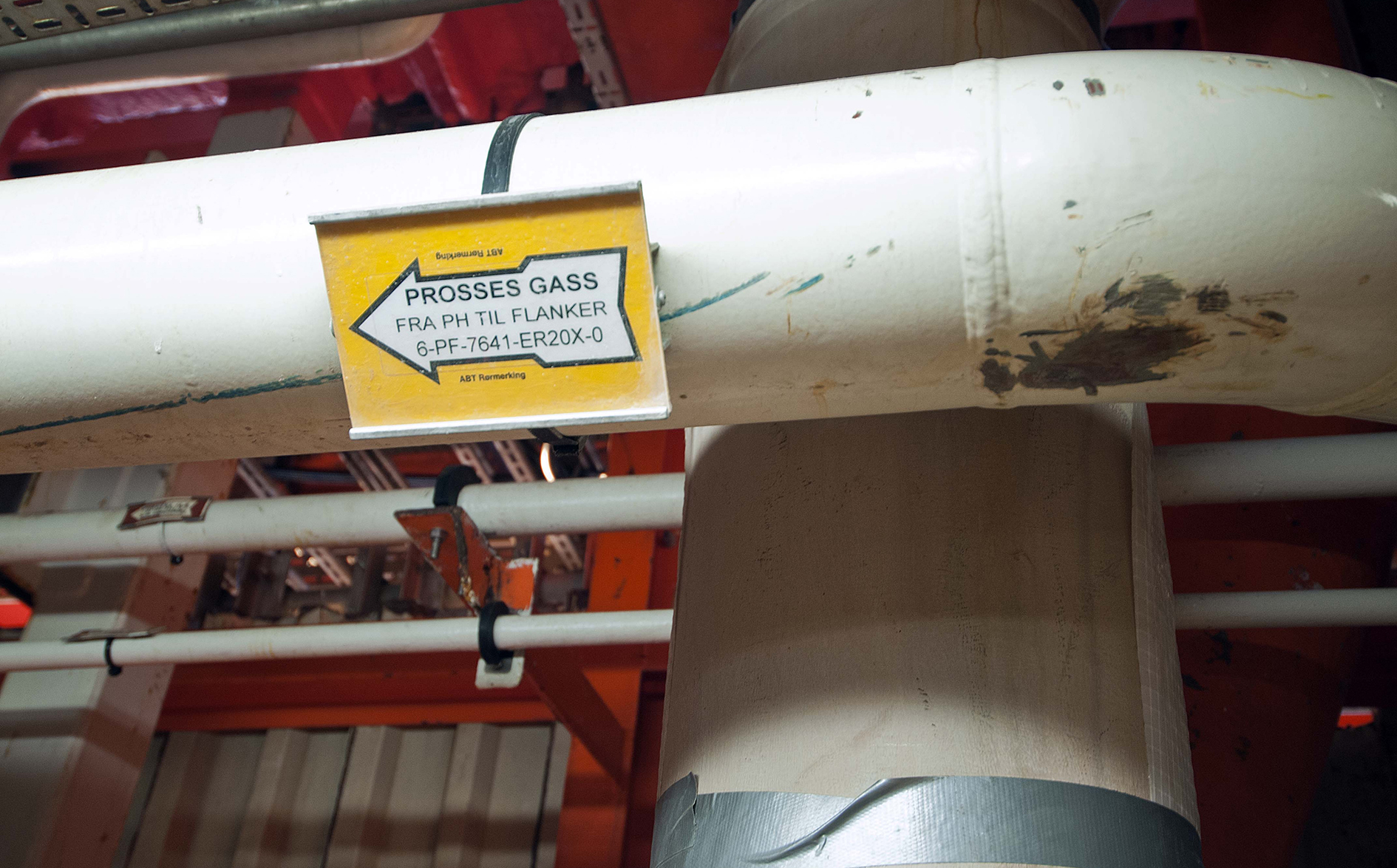
Gas, oil and water from the sub-surface reaches the surface via wellheads on three different platforms at the field centre and are piped over the connecting bridges to the PH structure. Pressure from each valve is reduced by chokes before the wellstreams are comingled in the production manifold and led to the first-stage separator. In addition, output from Hod and the two flank platforms arrives at the field centre through flowlines and reaches the PH topsides via risers. Originating a few kilometres from the field centre, these flows are blended with oil and gas from the field centre before entering the first-stage separator.
Oil treatment
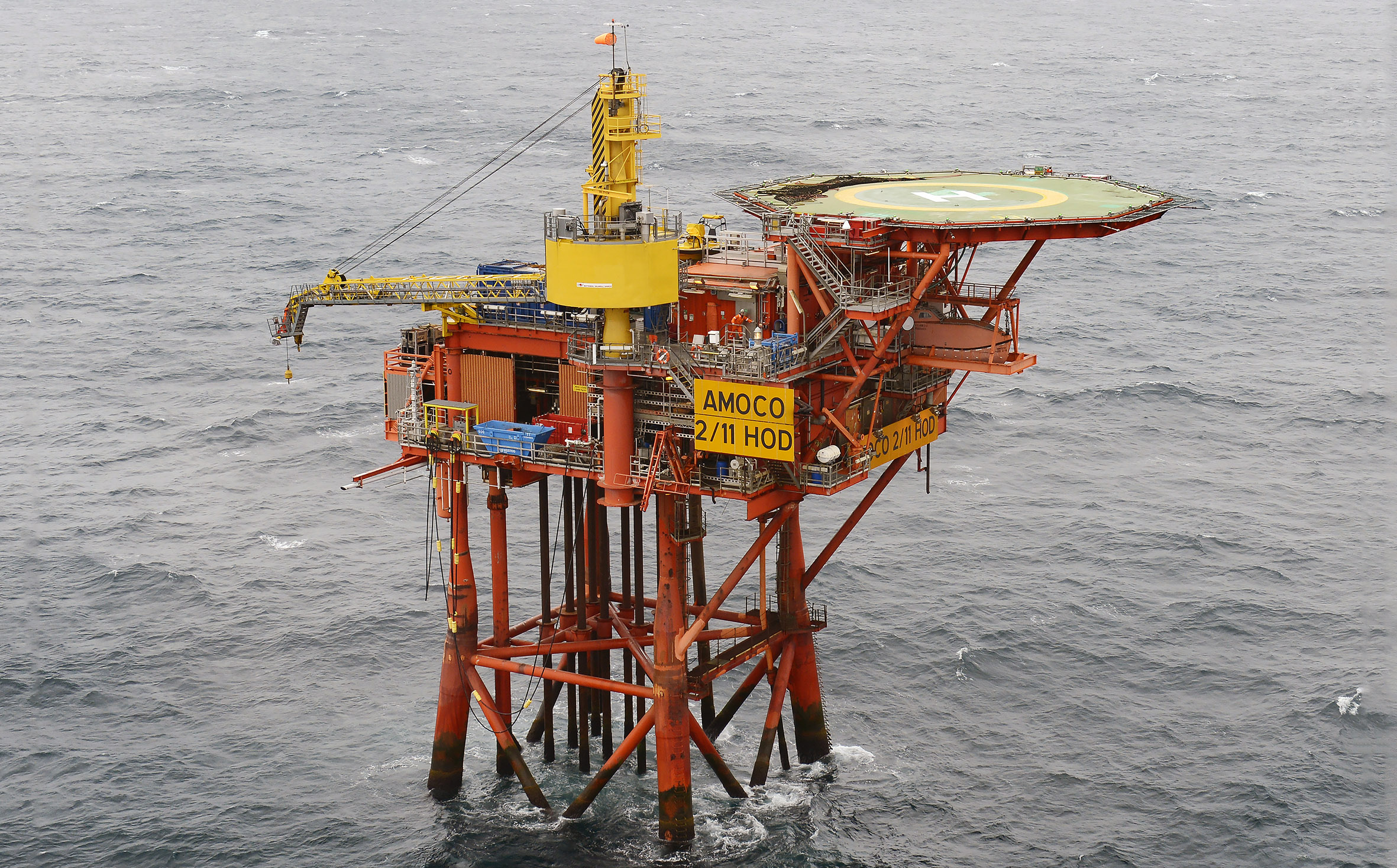 Utbyggingen av Hod, forsidebilde, feltet,
Before the wellstream enters the first-stage separator, it is raised to 50°C in the inlet heaters to improve separation of water and oil and to boil off some of the gas. Heating is required because output from the satellite platforms – Hod and Valhall Flank North and South – cools in the flowlines from the reservoir temperature of 60°C.
Most of the gas and produced water is separated from the oil in the first-stage separator, which operates at a pressure of four barg and a temperature of 50°C. Produced water is sent to the treatment facility for removal of residual oil and other hydrocarbons before being discharged to the sea. Gas goes to pressurisation and treatment for export.
 Valhall flankeplattformer, forsidebile, feltet,
A multipurpose separator installed in parallel with the first-stage unit can be used for such activities as well-testing, normal production or reception of output from “difficult” wells. Past the first-stage separator, oil pressure is reduced to about two barg for second-stage separation and heated to 60°C to remove enough to the gas to meet oil export specifications. The second-stage separator removes the remaining gas and produced water from the oil, and the gas pressure is raised with the aid of an ejector. That allows it to be mixed with gas from the first-stage separator for further processing, while the water is also mixed with water from the first stage before treatment. Oil has its pressure raised from the second-stage separator through two pump stages before being introduced to the export pipeline which runs via Ekofisk to Teesside in the UK.
Gas treatment
Gas pressure is stepped up from the first-stage compressor to the export level via four stages, and is cooled before entering each of these. That causes some liquid to separate out in scrubbers. Operating parameters are:
| Component | In | Out | ||
| Pressure | Temperature | Pressure | Temperature | |
| First-stage compressor | 4 barg | 25 o C | 12 barg | 115 o C |
| Second-stage compressor | 10 barg | 25 o C | 37 barg | 115 o C |
| Third-stage compressor | 35 barg | 25 o C | 77 barg | 80 o C |
| Fourth-stage compressor | 43 barg | 25 o C | 120 barg | 120 o C |
Gas from the fourth-stage compressor is cooled down to 40°C before being sent to the metering station and then on through the export pipeline. A dehydration system to remove water from the gas is installed between the second and third compressors to avoid hydrates forming in the gas treatment system and export pipeline. This is achieved by absorption in glycol contactors, with triethylene glycol flowing down through the tank interior and attracting water molecules in the gas flowing up. The tank interior is shaped to ensure the largest possible contact surface between gas and glycol, and operates at 35 barg and 25°C. A scrubber is installed in the upstream glycol contactor to remove condensed liquid from the gas arriving from the second-stage compressor’s outlet cooler. Light liquid components are recovered from the gas in a treatment facility between the third- and fourth-stage compressors. This achieves the right calorific value and quality for direct transmission to the market as sales gas. Gas at 25°C from the third-stage outlet cooler has its temperature further reduced over a Joule-Thompson valve. This cooling and pressure reduction produces a temperature of -38°C in the cold separator, causing light liquid components to separate out and meeting the gas export specifications.
Gas and liquids from the cold separator are returned to the gas-to-gas heat exchanger, where they are heated by the hot gas from the third-stage compressor outlet cooler. The liquid is them recycled back to the scrubber for the third-stage compressor, with the gas sent to the fourth-stage compressor and on to export.
Condensate removed in the third-stage scrubber is sent to the NGL column, which boils off the lightest components. This ensures that the residue contains so little gas that it can be pumped to the oil pipeline for export. The NGL column operates at 18 barg and has a temperature of roughly 25°C at its base and 0°C at the top.
Source:
Torbjørn Selanger, e-mail spring 2015
Value creation 1982–2012New process and hotel platform on Valhall