
The original process

Valhall PCP (1983-2012)
Oil treatment
 Den opprinnelige prosessen
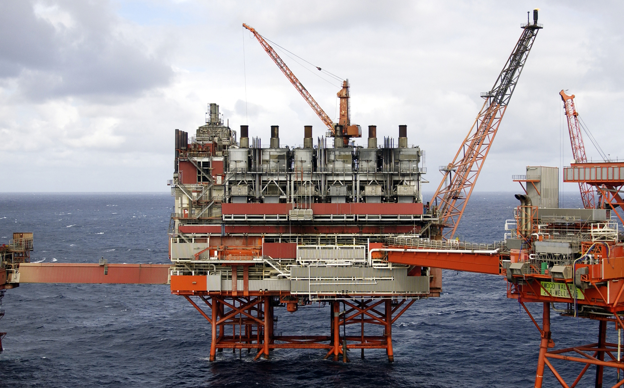
Oil and gas from the drilling platform (DP) were piped over the bridge to the PCP, which also received bridge-borne output from the wellhead (WP) and injection (IP) platforms installed some years after production began. Wellstreams from Hod (producing from 1990) and the two flank platforms installed immediately after 2000 arrived on the PCP via dedicated flowlines and risers.
Liquids in the reservoir are at a temperature of about 60°C, but output from the two flank platforms cools down en route to the field centre. This flow must pass through an inlet heater before being mixed with the other wellstreams in order to achieve good water-oil separation and to improve separation of gas and oil.
The platform accommodated two parallel first-stage separators (1 – the diagram shows only one production train), which separated most of the gas and water from the oil. These separators were originally designed to operate at a pressure of seven atmospheres and a temperature of 60°C with the incoming wellstream. Over the years, however, both pressure and temperature in the reservoir declined, and the separator pressure was reduced accordingly to achieve optimum production. The produced water separated out in this stage was sent to a treatment facility for removal of residual oil and other hydrocarbons before being discharged to the sea. Gas was led from the first-stage separator to its compression train in the production train after the main stream had passed through the first-stage compressor (7) for pre-export pressure boosting and processing. From the first separator, the wellstream was heated to 70°C (2) to drive out more of the gas dissolved in the oil before it entered a second separator (3) to remove more gas and water. Gas from here was led back to the compression train via the first-stage compressor. Water was sent for treatment with water from the first-stage separator. Oil in the wellstream was now free of the other components and could passed via a pump (4) to the export pipeline.
 Produksjonsplattformen PCP, forsidebilde, feltet,
The wellstream passed through yet another heat exchanger (5), which ensured that the gas reached its prescribed temperature of 30°C before entering a tank (6). This ensured the removal of even more water as well as of the heavier hydrocarbon components known as condensate, which were used as fuel in the PCP’s power generation system.
Pressure in the gas was now boosted with the first-stage compressor (7) so that it could be blended with gas from the first-stage separator for further processing. The water was once again sent for treatment along with the water from the first-stage separator.
Gas treatment
The gas pressure was raised from the first-stage compressor to export level through seven compressor stages (5, 8, 11, 13, 16 and 18), which reduced its temperature at each step. This meant that some water and condensate separated out and was removed in vertical scrubbers (6, 9, 12, 14 17 and 19) before the gas entered the next series of compressors (7, 10, 15, 20, 22 and 23). Condensate from the scrubbers was piped via the feed tank for the stabiliser column and then to the column for natural gas liquids (NGL).
Operating parameters were:
| Component | In | Out | ||
| Pressure | Temperature | Pressure | Temperature | |
| First-stage compressor (7) | 1 barg[REMOVE]Fotnote: Barg = bar gauge. Pressure in bars above ambient or atmospheric pressure. One bar equals approximately atmospheric pressure. | 30 o C | 7 barg | 120 o C |
| Second-stage compressor (section 1) (10) | 6 barg | 120 o C | 13 barg | 80 o C |
| Second-stage compressor (section 2) (10) | 13 barg | 30 o C | 26 barg | 80 o C |
| Third-stage compressor (15) | 25 barg | 30 o C | 85 barg | 128 o C |
| Expander recompressor (20-22) | 49 barg | 20 o C | 63 barg | 40 o C |
| Final-stage compressor (23) | 63 barg | 40 o C | 88 barg | 72 o C |
| Export compressor (not shown) | 87 barg | 30 o C | 125 barg | 72 o C |
The export compressor was installed around 2000.
Gas from the export compressor was cooled down to 70°C before being sent to metering station and then on through the export pipeline. Glycol was injected (not shown) after third-stage compression in order to extract water from the gas, and removed downstream from the scrubber. Such dehydration is intended to inhibit the formation of hydrates (hydrocarbon ice) in the gas treatment system and the export pipeline.
A gas treatment facility (21) stood between the third-stage and export compressors to remove light liquid components from the gas. This ensured the right calorific value and quality for direct transmission to the market as sales gas.
Gas at 27°C from the third-stage outlet cooler had its temperature further reduced in a gas-to-gas heat exchanger before being lowered from 85 barg to about 50 through a turbo-expander. This cooling and pressure reduction produced a temperature of -14°C in the cold separator, causing light liquid components to separate out and qualifying the gas for export. Gas from the cold separator passes through a recompressor driven by the turbo-expander before warming up in gas-to-gas heat exchangers. It was raised to export pressure in the final-stage compressor and the export compressor installed around 2000.
Condensate removed in the cold separator has its pressure reduced and is mixed with liquid from the scrubbers via the stabiliser column’s feed tank to the NGL column. The lightest components were boiled off there to ensure that the residual condensate contained so little gas that it could be pumped into the oil pipeline for export. Operating at 18 barg, the NGL column had a temperature of about 155°C at its base and 9°C at the top. Gas from the column was used as fuel in the platform’s power generation system.
Source:
Process description from Torbjørn Selanger, e-mail, spring 2015.